Enclosures & Cases
Framework Portable handheld Case (Beth Deck rev. 1.5)
SKU 3DPW-pr-1051411
$200.00NZD
In stock · Made-to-order resin · Ships from Auckland · Free shipping over $75
- Material
- PLA (filament)
- Colour
- Grey
- Weight
- ~40 g
- Print time
- ~4.5 h
- Shipping
- $10 std · $20 express
- Lead time
- 1-3 d print + 1-4 d ship
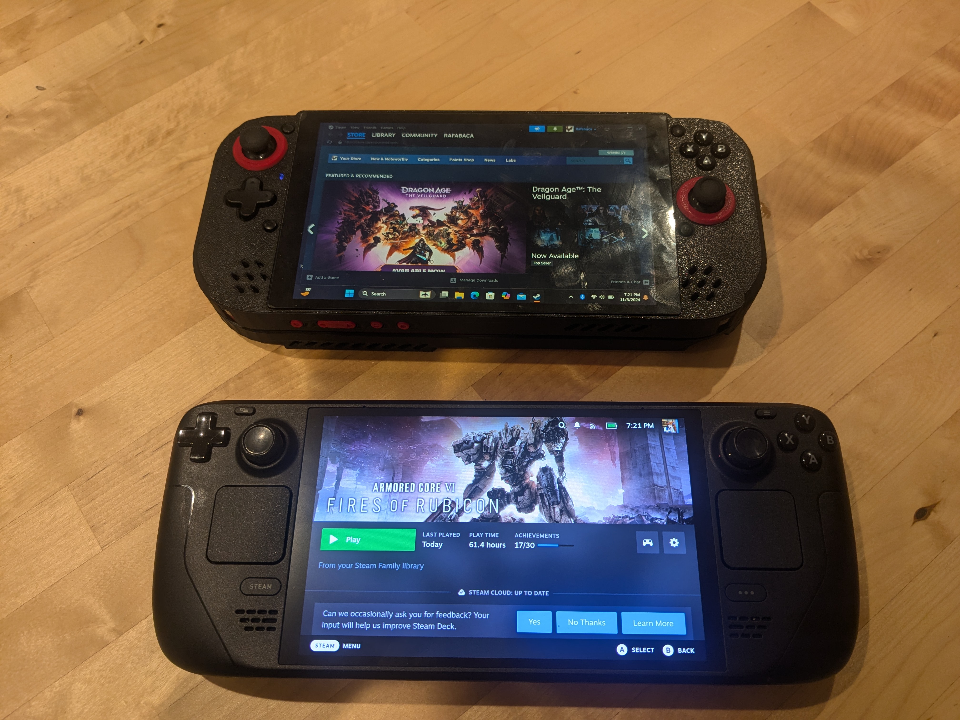
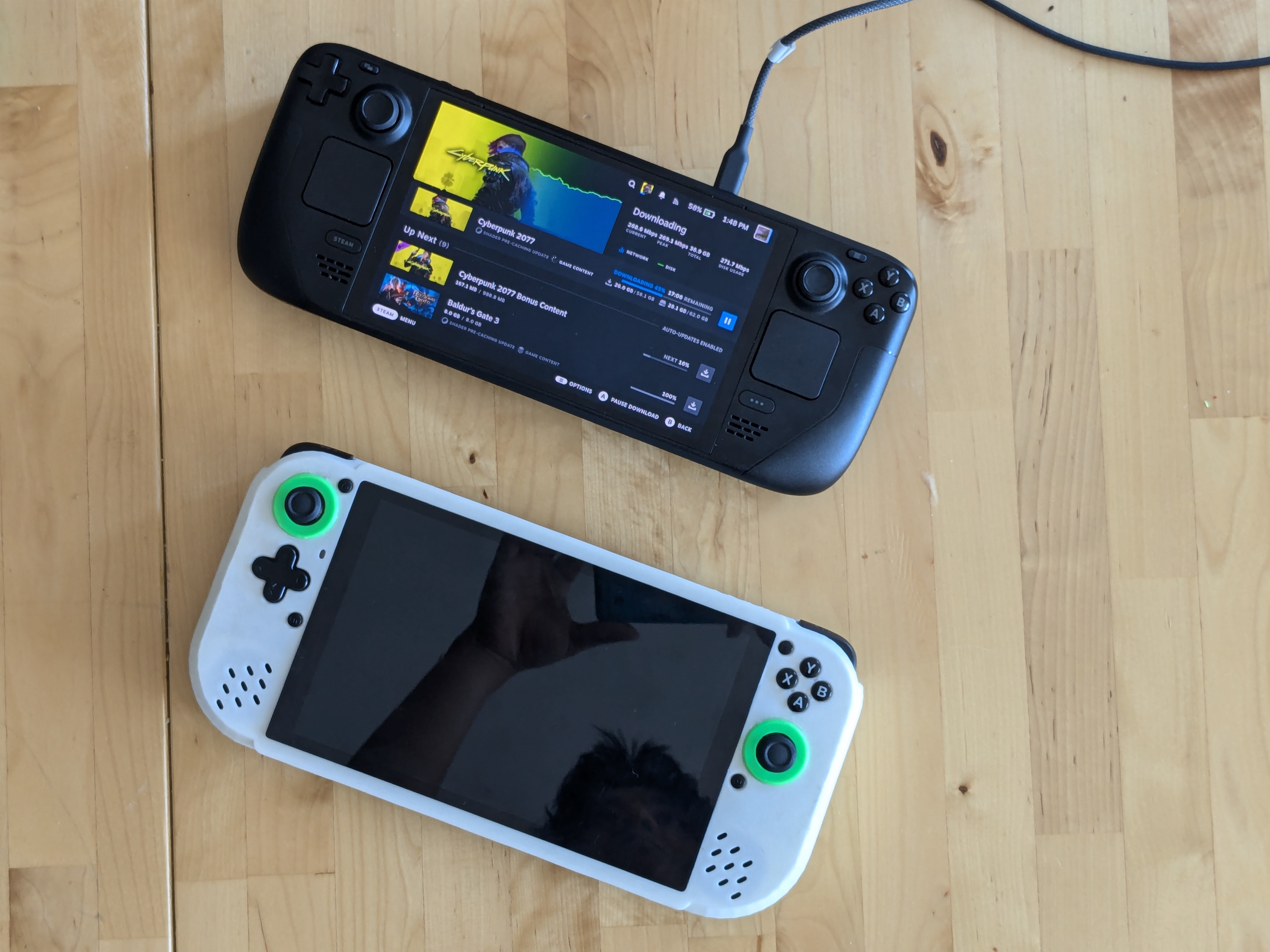
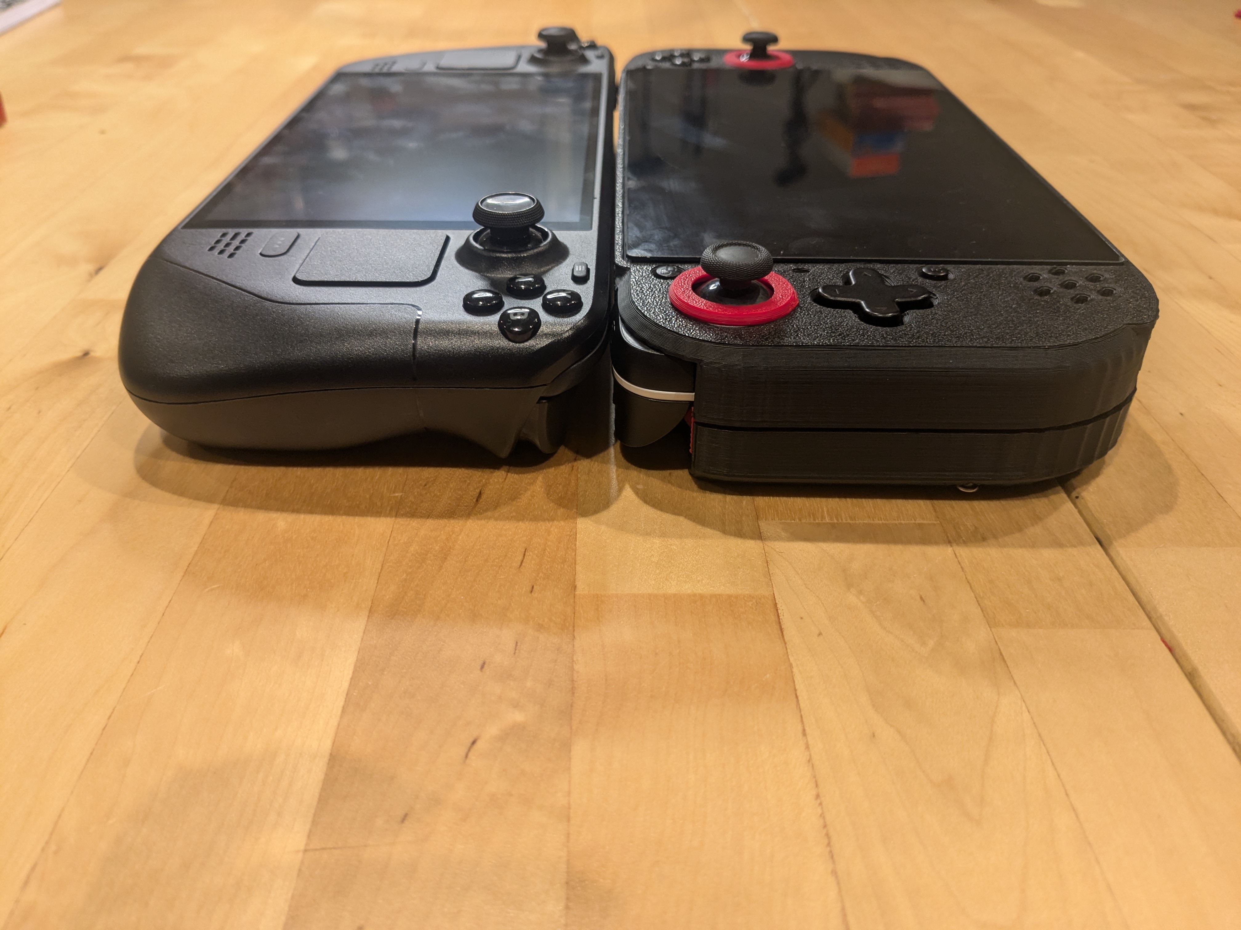
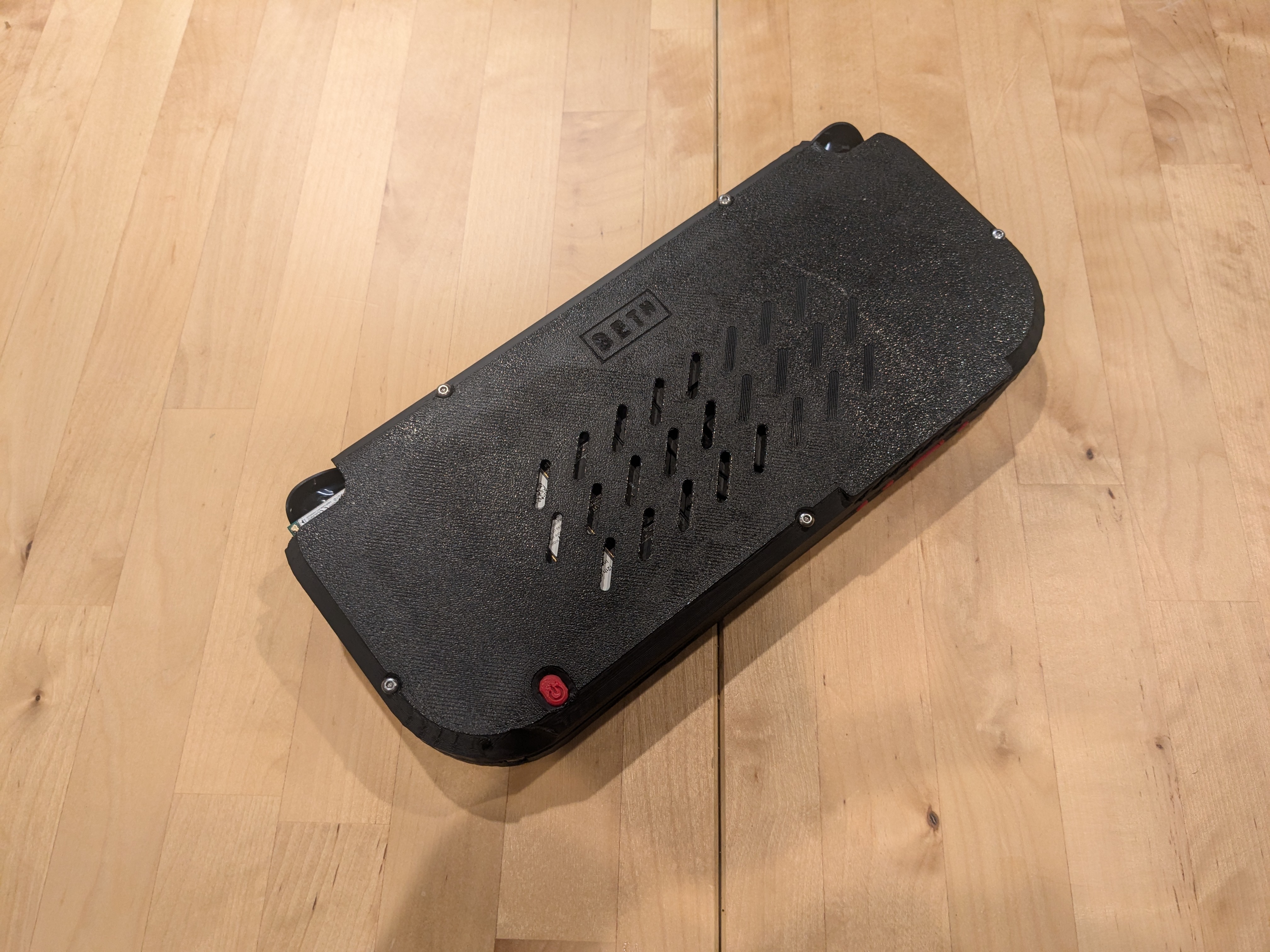
UPDATE: 1.51 -reduced amount wifi card sticks out (11/25/24) UPDATE: 1.5 Has been released! -The case has been reduced in size and enforced in key areas. -Added external screen controls. -New power button, still goes missing but it's new! -Better airflow. cools down the battery and other components better, and no longer has overheating issues. Performing 2,600 points higher than average with an intel 1240p in future Mark's night raid. -Reduced number of M3x25 bolts from 6 to 5. -Thunderbolt port moved closer to the center for better ergo. --NO NEW PARTS NEEDED! Future release -Beth Dock: a dock for your Beth Deck. -Beth Deck Standalone: Bottom case for beth deck so you don't need framework hardware to use it. -Beth Deck Raspberry Pi bottom case: support for Raspberry Pi. -Beth Deck 2.0: custom PCB and layout. slimmer, smaller, better speakers, easier to assemble. Are you tired of buying the newest gadgets only to throw them away five hours later because the next best thing just came out? Introducing the Beth Deck, The future-proofed completely upgradable handheld. Guaranteed to always play the latest games and apps far into the future! (as long as Framework continues to support their 13" mainboards) The whole thing can be assembled in about 15 minutes and disassembled in less than 2 minutes with no soldering and all non-printed parts can be purchased! Parts list 5X M3x25mm button head screws 6X M3x5mm button head screws 5X M3x4mm heat set insert 1X M2.5x4mm Standoff 4X M2.5x8mm 1X Easy SMX M05 Gaming controller 1X USB-C dongle with 2xUSB-A, 1xUSB-C and HDMI 1X Waveshare 8" 800p touchscreen 1X 100mm USB-C extension (CMST-CF) 2X 100mm 90-degree USB-C to USB-A adapter (CMUP-AMST) 1X 200mm HDMI Ribbon cable (A1-A1) 1X Wifi antennas 1X VHB tape 1X USB-C 90-degree adapter ( For the USB hub, this one is smaller than the other) 1X USB-C 90-degree adapter (For charging and docking) 2X 1.25" speakers (They need soldering, but they sound much better in the new case. Maybe everything being more compact helped? I don't know.) Framework 13" mainboard Framework 13" battery (RAM, SSD, Wifi card not included) INSTRUCTIONS TO BE CLEAR, I'VE PUT THIS TOGETHER IN 15 MINUTES, BUT I'VE DONE THIS LIKE 20 TIMES. TAKE YOUR TIME. YOU'll SAVED MORE TIME BEING CAREFUL, I PROMISE YOU PLA does not work; it's too brittle. The top shell has many small features designed for injection molding. Watch out for warping. The controller might not work properly, specifically, the triggers that use Pogo pins. Use materials like ABS PETG or Composites. Depending on your materials, you might have to change your settings to compensate for warping. Make sure you have all the components. Disassemble the SMX Controller down to its individual components and keep all the screws. Keep both PCBs connected by their ribbon cables but disconnect the joy stick PCBS. Remove the USB hub from its enclosure by removing the plastic clip on the front and back. Place M3 heat-set inserts into the top shell of the beth deck. You can look up how to do this on YouTube if you don't know how. you can do it with a soldering iron or a lighter and a M3 bolt. try to get it straight in though. Prop the LCD screen by 15mm (~½ inch) and fit the top shell onto the screen. It should snap into place without much pressure, but if you have to apply pressure make sure the bottom side is supported so you're not bending the screen. Populate all the button locations, They are indexed so it's hard to put the wrong button in the wrong spot, also place the LED indicator light defuser, Make sure all the control holes are populated ( X,Y,A,B, Select, Start, FN, Menu, D-pad and LED diffuser) then place the button membrane on to the right buttons and the D-pad, they're not simular so if it doesn't fit right, try the other one. Now slide the L1 and L2 bumpers into the top studs. you can leave the springs out for softer clicks, but can sometimes be unreliable With the controller PCB connected, place the top ends into the shell and push down the bottom, you might need to slide them around a little bit until they fit. Once flush, check if the bumpers click and return by pushing them down and tightening the bottom screws on the left and right PCBs Now lightly screw in L2 and R2 analog triggers, make sure the hall effect sensors have not fallen out, and that the pogo pings are directly on the contact pads. With the Screws not tightened, check to see if L1 and R1 bumpers work and lightly tighten each screw until you feel slight pressure. Check to see if the bumper buttons still work. if they stop clicking, lightly unscrew the analog triggers until the bumpers work Trim the unused battery housing on the left side (right if upside down). It's not used and on some of the shells I've printed, it gets in the way of the joysticks. Plug the joysticks into their ribbon cables and gently tighten them on their post. These are delicate so just lightly hand tighten them. The plastic will prevent the bots from walking out. Plug all extension wires into their proper locations, don't mind my custom USB C to a cable. Place some electrical table on top of the HDMI port. This is where the USB-C hub will go and the tape will prevent any shorts as a precaution. If you are using the speakers trim one side of the speakers to follow the radius of the driver and solder the correct wires onto the 4-pin JST connectors (R+L+R-L-) Then press fit them into their slots, it should fit with firm pressure. Place the screen control buttons in their slots on the bottom of the shell. use a small flat-head screwdriver to fit them in their slots tilt the case at an angle so they don't fall out and place the screen control PCB in the adjacent slots. Plug it into the port to the left of the speaker port Place the screen mount over the screen and route all the wires to the top of the screen holder, where there is a missing leg on one side. The HDMI cable will have to make a 90-degree bend to the side of the missing leg. With the wires routed, fasten the screen on the screen mount with the M2.5x 8mm screws. Route the USB hub wire under the right leg and plug in all the ports. The USB-C cable should plug into the port close to the HDMI. the other port is only a power port and won't work. Plug in the smaller 90-degree adapter and check your work. Use another computer or use your framework mainboard to check the beth deck. plug in the beth deck make sure the LCD is working then go to GAMEPADTESTER.com and check that all controls are working. Place ducting tape on the bottom side of the battery. This isn't necessary but it's a good precaution Now install the battery into the mid-frame. Screw the capsulated screws into the plastic shell and use a 5mm M3 bolt to tighten the battery bracket on the opposite side. Use VHB table to secure the wifi antennas on opposite sides of one another and route the wires on the wire guides near the walls of the mid-frame. Pull the battery connector through the slot on the left side and plug it into the main board, this can be finicky so do this before bolting the board in. Place stand-offs on the left right and bottom of the main board and the mid-frame and lightly tighten with M3 by 5mm screws. If the left and right stand-offs aren't fitting correctly, they are likely reversed. Placed the M2.5 stand where the wifi card will go near the right triggers. insert wifi card, screw in place, and tighten the rest of the screws. Plug in the wifi antennas and and the larger 90-degree USB-C adapter and your done! One more step Now we just have to put all the parts together. Slide the USB-C hub wire into the left slot of the mid-frame, and connect it on to the bottom USB-C port (the top is easier but on AMD motherboards the top USB does not have video out. So use the top if you are using Intel, it's just easier) THIS LITTLE SHIT! MAKE SURE ITS IN THERE. TAPE IT ON THE OPPOSITE SIDE IF YOU HAVE TO. PLACE IT LIKE THIS! Then fit the other half of the Beth Deck on top and make sure it fits snuggly. Screw in the 5 M3x 25 bolts and you're done. Power up and enjoy! Keep in mind the area directly under the fan is covered because the fan is responsible for cooling not only the CPU but all the laptop's components, including the battery. I ran into overheating issues when air had a direct path to the fans. Small issues -the mobile controller is difficult to work with. You should ensure ribbon cables are completely inserted or the controller will do wonky things. Be careful screwing in parts, stop when they are just starting to tighten and do not go any further. Plastic acts like locking compound, don't worry about under-tightening. it will break if you over-tighten. -Power button still flies off and out the window when disassembling.
Tags: case, controller, portable, framework, steamdeck, resin print, nz made, made to order
Design credit: Original design by Beth Le - licensed under CC0.
View original model + STL files on Printables ↗
View original model + STL files on Printables ↗
Frequently asked
How long does shipping take?
Framework Portable handheld Case (Beth Deck rev. 1.5) is printed to order. Lead time is typically 1-3 business days plus 1-4 days NZ shipping. Standard NZ shipping is $10, free over $75.
What material is this printed in?
By default this is printed in PLA (filament) at 0.025 mm layer height on an MSLA resin printer. Custom material and colour swaps are available, just leave a note at checkout.
Can I get this in a different colour?
Yes. Every product can be printed in any of the resin colours we stock, or hand-painted on request. Leave a note at checkout or email hello@3dprintworld.co.nz.
Do you ship outside of New Zealand?
Currently New Zealand only. Australian shipping is coming.
Who designed this?
Designed by an independent sculptor and licensed for commercial printing. The original is linked on this page.